Overview
Creating, loading and saving UML models
Editing and naviagting UML models
The model and metamodel browsers
The property sheet
Supported UML diagrams
Importing instances from other tools
Overview
OCLE allows you to import UML models realized using other state-of-the-art CASE tools, such as Rational
Rose, TogetherSoft ControlCenter, Gentleware Poseidon or NoMagic MagicDraw. The
precondition is that these models are stored in XMI format. OCLE currently
supports a variety of XMI versions, even though not all CASE tools fully
conform to the OMG standard. OCLE also allows you to create your own UML models
inside its graphical interface and then export them to XMI files, so that you
can use them in other tools. Particularly, to reduce consumed disk space, OCLE
automatically packs the resulting XML files into a ZIP archive. Currently, UML diagrams produced
in OCLE are also saved in XML, but using a proprietary DTD.
In OCLE, models can be used either independently or attached to an OCLE
project (see project management
for details). One model is the active model. The contents of the active model is
always displayed in the model browser.
Creating, loading and saving UML models
These options are available in the Model menu of OCLE. To create a new empty model, select the New option. An empty model, named 'NewModel' will be created and displayed in the
model browser. To load an existing UML model, select Open from the Model
menu (or click the corresponding  toolbar button).
OCLE will allow you to browse for both XML and XML.ZIP files (which
are generated by OCLE when saving UML models). To save the content of the active
model, choose Save or Save as… from the Model menu. The active model will
automatically be packed into the XML.ZIP file you specify at the first save
request.
Editing and navigating UML models
OCLE provides powerful model editing and navigation facilities. These include the model and metamodel
browsers, the property sheet and three types of UML diagrams.
The model and metamodel browsers
The active model is displayed in the model browser.
The main role of this browser is to allow full model
representation and navigation. Also, the browser supports customization by
letting the user configure a filter to be applied on the types of the model elements represented in the browser.
Finally, the browser allows you to edit the model by adding and removing
elements.
The browser displays model elements in a way that conforms with the composite
relationships in the UML metamodel. Every element is displayed with a name and
a suggestive icon. These two characteristics help the user easily identify and
differentiate the elements. If the model element does not have a name, a
default one is displayed. The icons describe the type of the elements. A few
icons may offer additional information about the elements (attribute and operation
icons, for instance, are specifically designed to suggest the visibility of the represented feature). The model
browser also provides suggestive tool tips for the elements it displays; these
are useful when the elements representations are too large to fit in the
browser window.
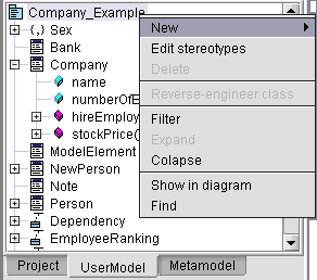 |
Fig.1 The User model browser |
The browser provides two mechanisms for locating
elements. The popup menu of the model browser lets the user search the browser
for a certain model element (in a large model it can be difficult to manually
find an element; also, sometimes you need to look up for more related elements)
or to locate an element in the existing diagrams.
The Find in browser dialog is displayed in figure 2 below:
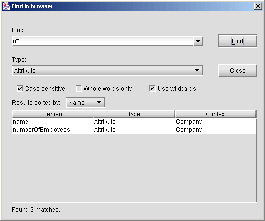 |
Fig.2 Finding elements in the model browser |
In the Find: region, the user types the text to
find or selects it from the history combo box. Elements are searched by their
name, not by their representation in the browser. Therefore, you may leave this field blank, meaning that element names will be ignored when searching.
The Type: combo box lists all the
types shown in the browser (see Filters below, option '<any type>'). These types are in fact the metaclasses in the UML 1.5 metamodel.
If the '<any type>' option is selected, all elements are searched. If a
specific type if selected (e.g. 'Class', 'Attribute', 'Parameter' and so on)
only elements of that type are considered by the search. The Use wildcards option specifies
if the text to find should be used as a regular expression or not. Regular
expressions use '*' for zero or more characters and '?' for a single character.
Search results are sorted alphabetically and displayed in
a table with three columns. The first column contains the name of the
element, the second its type and the third contains the context within which
the element is defined (e.g. an attribute with the same name can be defined
in two classes).
In the example above we searched the Company Example model for attributes
having their names starting with 'n'. In this case, two attributes were found, 'name' and
'numberOfEmployees', both located in class 'Company'. Clicking on an item will select that element in the model browser.
The Show in diagram request will lead to a search
for the selected element through all loaded diagrams. The diagram that contains
the selected model element will be activated for editing. If more than one
diagram contains the element, the user is asked to select one for editing (see also supported UML diagrams).
When displaying model elements, the browser applies
a filter on them. The filter is responsible for selecting the elements that
will be represented in the model browser. The filter holds two lists of
elements, one representing the elements that will be shown and another
representing the elements that will be ignored by the browser.
However, the hidden elements exist in the model and they can be referenced by
other means (e.g. property sheet, OCL expressions). They are not shown in the
model browser for readability. A few elements (e.g. Model,
Package) are always shown in the browser, because without their presence it
would be impossible to navigate the model.
The Browser customization dialog is shown in figure 3 below.
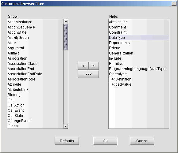 |
Fig.3 Browser customization |
The list on the left holds the types of elements to be
shown in the browser; the list on the right shows the types of elements not
to be shown. You can double click on an element to move it from one list to
another. Also you can select more types and press the 'Show'  or 'Hide'
 buttons, according to your intentions. To show all
types simply press the 'Show all'
  button.
Pressing the 'Defaults' button, the filter is reset to the default configuration, which is
shown in figure 3 above.
The context sensitive browser popup menu provides the user
with the means to edit the model: create and remove elements (except relations
which can be added only through the diagram editors) and diagrams, create and
set stereotypes. When an element is created, its attributes (properties) are
set to default values so that the Well-formedness Rules are satisfied (OCLE 2.0
does not yet fully implement this requirement). The properties may be
modified using the property sheet (see below).
Stereotypes are treated in a special way. When created, they are always linked
to the model, as owned elements. The 'base class' attribute is initially set
to the type of the element where they have been created. Stereotypes are attached
using a dialog that displays all the stereotypes that can be applied to
the selected element. The user can select stereotypes by marking the check boxes on the
left (see figure 4).
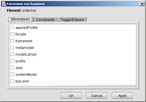 |
Fig.4 Attaching stereotypes |
When OCLE starts, the UML 1.5 metamodel is loaded.
This model is loaded only once and is set to be read-only. If you want to load the UML 1.5 model for
performing operations upon it, it is strongly recommended that you make a copy
for this purpose. Loading this project from the 'metamodel' directory of the
application and altering it may result in future malfunctions.
Beside the user model browser, OCLE also provides a
metamodel browser. Both the model and the metamodel browsers share the
property sheet. This means that when you select an element in either of these
browsers, its properties will be displayed by the property sheet. The metamodel browser allows for the same operations as the
ordinary model browser, except for editing operations (creating and removing
elements).
The property sheet
The property sheet is a grid that displays the
individual properties for an element (e.g. name, visibility, owner, stereotypes and so on).
The main responsibility of the property sheet is to
provide a view on an element from the model and a mechanism for modifying its
properties. It is also possible to navigate between related elements (e.g. from
a class to its attributes and vice-versa).
The property sheet has two columns. The column on the left shows the names of the properties while
the column on the right shows their values. The grid provides appropriate editors to change these
values. For properties having (almost) infinite value domains, such as 'Name' or 'Initial value', a text box is used. After editing the value of such a
property, you must press 'Enter' to update it. For properties having finite value
domains, such as 'Visibility' or 'Type', a combo box with all possible
values is provided. A property whose value is another element (such as the owner of
an attribute or operation) has an associated button that allows you to navigate to the
referred element.
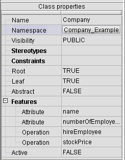 |
Fig.5 The Property Sheet |
If properties are queried upon a malformed element an
error message will be displayed in the Messages panel. Usually this happens when properties are not set for some
elements. Warnings may be raised if properties are set but have an unexpected
value (it is the case when a property’s value is out of the possible range).
Some properties (e.g. stereotypes, attributes,
operations etc.) are grouped into collections that can be expanded or collapsed
depending on the user needs, as shown in figure 5.
Supported UML diagrams
OCLE supports (in its current version) three kinds of UML diagrams:
Class Diagrams
Use-Case Diagrams
Snapshot diagrams
In order to create any kind of these three diagrams, right-click in the model browser
the model element which you would like to be the parent for that diagram (this element can only be a package or the model itself). From
the pop-up menu that appears, select New and then the kind of diagram
you want:
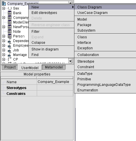 |
Fig.6 Creating a new Diagram |
Class Diagrams
Once you have created a new Class Diagram, the Worksheet together with the specific toolbar appear:
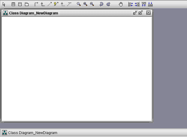 |
Fig.7 The Worksheet and the Toolbar |
The Worksheet is where you place the objects in the Diagram. The toolbar is where you select these objects from.
There are 2 ways in which you can use class diagrams:
1. To see graphically elements that already exist in the model
2. To create new elements / relations
1) In order to see elements that already exist in the model, you drag & drop them from the browser onto the Worksheet. Please
note of the following when drag & dropping:
1. Although you can drag & drop any kind of model element onto the class diagram, only classes, interfaces
and packages will be represented.
2. The relations between them (that already exist in the model) will be automatically drawn. Moreover, dragging a relation from the browser
to the class diagram has no effect.
2) In order to create new elements / relations, you use the toolbar:
-
The select  tool enables you to select any kind of object in the diagram, including relations. If you select
a single object, it will automatically be displayed and selected in the browser and its properties will be shown in the property sheet.
Please note that the browser displays the selected element only if the current filter allows it. For more information on the browser and the
property sheet, please refer to the section on model navigation. However, using the select tool, you may select
multiple objects. To do this, select the desired elements in the diagram holding down the CTRL key.
-
Creating elements - you simply
click the button for the element you wish to create (Class, Interface or
Package) and then click on the Worksheet. The element will appear in the
diagram and will also be created in the model. If
you wish to create more elements of the same kind, without having to
repeatedly click the toolbar button, you can hold down the CTRL key,
click the button, and while CTRL is down you can click on the
worksheet. A new element of the selected kind will be created for each click.
-
Creating relations – to add a relation between 2 elements, you click the toolbar
button for the desired relation type (Association, Generalization,
Dependency, Permission, Realization or Association Class), then click
the element which will be the source and drag the mouse to the element
which will be the target. Please note that for
association classes, the source of the relation must be the class you
wish to convert to an association class and the target the corresponding
association.
-
Zooming – allows you to increase/decrease the scale of the diagram.
-
Undo / Redo – in the current version of OCLE, undo/redo may be used only
at the graphical level, meaning that any changes to the model cannot be
undone. Only the movements and insertion/deletion of objects in the diagram
can be undone.
-
Quick View – allows
you to see an overview of the active diagram. It can be very useful for large
diagrams. Please note that selecting objects and relations in the quick view
window will also trigger their selection in the diagram target diagram.
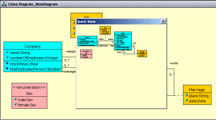 |
Fig.8 Class Diagram Quick View |
Please read the additional diagram info.
Use-Case diagrams
Use-Case diagrams behave exactly like class diagrams. They can be created and used in same way as class diagrams.
Please read the above section on class
diagrams. A use case diagram looks like this:
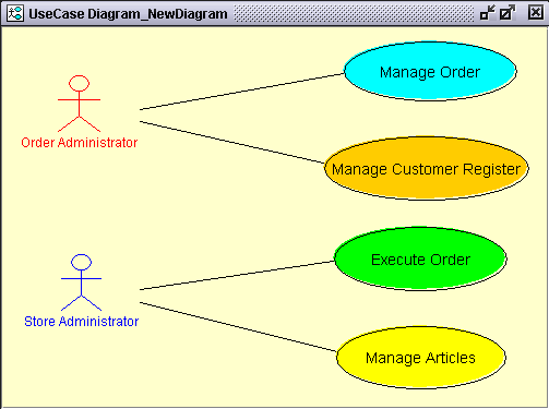 |
Fig.9 Use-Case Diagram |
The toolbar of a use-case diagram is to a great extent similar to the toolbar for class diagrams.
The only difference is the actor and the use case
tools, which allow you to add these two kinds of elements to the diagram.
Most of things like changing the graphical attributes, deleting
elements from diagram and modifying the properties are the same as for
class diagrams. Please read the additional
diagram info for more information.
Snapshot diagrams
Snapshot diagrams, which are a sort of object diagrams, are used to view and create objects and links between them.
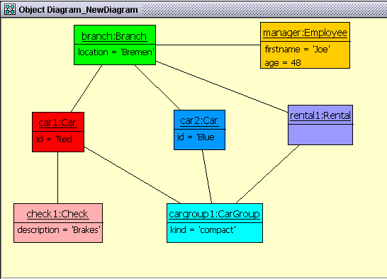 |
Fig.10 A Snap-Shot Diagram |
To create a new snapshot diagram, you will have to define (create) a collaboration. Once the collaboration is available in the model
browser, right click it and choose New and then Object diagram.
To create a new object in the snapshot diagram use the Object  toolbutton, or the model browser, by right-clicking a collaboration and selecting
New object. The instance creation dialog shown in figure 11 should appear.
You may use the model browser to create a collaboration
or you may import instances from other tools
in order to have a collaboration available.
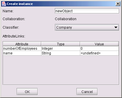 |
Fig.11 Instance creation dialog |
In this dialog you may specify the name of the new object and the class it
instantiates. Once you have selected the class to instantiate, a table appears
that allows you to specify the values of the attributes for the newly created
object. Click 'OK' to have the object created with the specified values and
the dialog closed. If you don't set the attributes' values, implicit values
will be set. To change the attributes values for an object, right-click the
object in the model browser and choose Edit Object. The instance creation
dialog will appear and you can set in the attributes table the values of object's
attributes.
Drag & drop is also available for snapshot diagrams. Once you have some
objects created / imported, drag them to the active snapshot diagram. Any existent
links between them are automatically drawn in the diagram. However, you may
create additional links between existent objects using the Link toolbutton. You will have to specify which association you want to instantiate.
For qualified link ends, an edit dialog will apear (see figure 12), where you
can specify the values of qualifiers.
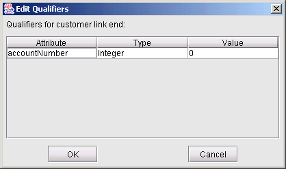 |
Fig.12 Edit qualifiers dialog |
If you don't set the qualifiers' values, implicit values will be set. To change
the values of qualifiers, from model browser choose the qualifier and go in
the property sheet and double-click the value property, then set the name of
the DataValue to the desired value.
Note: The instance creation dialog also becomes available when you draw
a link object between two objects on the snapshot diagram.
Additional information about diagrams
Graphical properties
It is possible to modify the graphical properties of the objects in a
diagram. Just right click the desired graphical representation. This will
bring up a popup menu that will allow you to modify attributes like: outline
color, fill color, title font size, body font size and some special things
as well. These special things include: adding attributes / methods, changing
the name of the element and filtering it. The ability to add an attribute/method and the filters property may only be
applied to classes. Filters allow you to choose what kind of
attributes/methods will be displayed for a class, according to their
visibility, as well as whether the stereotype of a class should be
displayed or not. The modification of graphical properties works for multiple selection also.
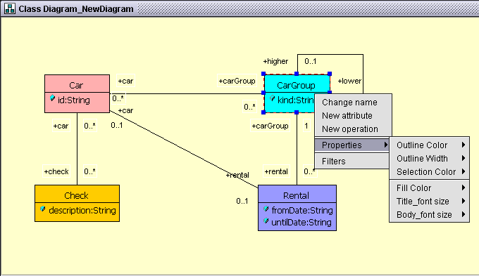 |
Fig.13 Modifying the graphical properties of the objects in a diagram |
Straighten lines
If you have a
relation (of any kind) between two objects that is not represented as a straight line, but broken into
many segments, you can straighten that line by selecting it, and then
holding down CTRL key + right click on
it. There are actually two modes in which the lines can be drawn in a
diagram (any kind of diagram): the free-form mode (which is the
default drawing mode) and the orthogonal mode which you can trigger
on/off by selecting the desired relation (graphical line) and pressing: CTRL
+ SHIFT + L. Also, if you have a relation or multiple relations
between the same two elements, you can use the CTRL +
SHIFT + K shortcut in order to arrange those relations.
Align association ends
An association has labels tied to its ends, which specify the role
name and multiplicity of that association. In a class diagram, these labels
are not tied to the association, meaning that you can put the labels
wherever you like. However, in order to avoid any confusion, double clicking
on an association will cause the roles to gather around the association ends,
accordingly.
Delete objects
Any object
(including relations) in a UML diagram can be deleted by selecting it and
pressing the DEL key. Deleting an object from a certain diagram does not
delete that element from the current model. The model browser should be used
for this purpose.
Diagram graphical properties
By right-clicking on
any diagram (but not on an element in it), you bring up a pop-up menu that
allows you to: change the background color of the diagram, show/hide the
grid and lock the diagram. Locking the diagram means that any
elements / relations will not be able to be moved until the diagram is unlocked.
Line control points
In order to add/remove a control point to an edge, you
simply right-click on that edge. This will
only work in the free-form drawing mode. Control points are useful when you
want to manipulate the lines in a more flexible way.
Handling diagrams in the model browser
Since UML diagrams are also displayed in the model browser, you may use this browser to rename, open or delete a diagram.
Clicking its name in the model browser will allow you to rename it in the property sheet. Right click the diagram in the browser and select
Open, Delete or Filter classes as desired. The Filter classes option is only available for class diagrams in this version.
Importing instances from other tools
Besides the capabilities to create class instances provided by the model
browser and snapshot diagrams, OCLE allows you to import instances from files generated by other
tools. Currently, two state-of-the-art tools are supported: the USE open-source
project and the ModelRUN commercial tool. This functionality is very useful when you want to evaluate
business constraints, because you need concrete objects (instances) to set the context for certain rules. Please
refer to model checking for details on business constraints evaluation.
Importing objects from USE
USE stores commands that create objects in CMD text files. OCLE is able to process
the commands in these files and create the corresponding objects. In UML,
objects are represented by the Object
metaclass, their attributes by the AttributeLink
metaclass and the values of the attributes by the DataValue metaclass, the associations by the Link metaclass and the association ends by the LinkEnd
metaclass. The properties for the created objects are set according to the values specified in the source CMD file.
Using the Import objects from USE … command from the Model menu you can select a CMD file to be imported into OCLE.
The effect of importing objects can be observed in the user model browser. The
objects imported for a class will be owned by that class. They are shown inside a collaboration specifically created for them. The collaboration
will have its name starting with 'Objects imported from USE'. Expanding the
corresponding collaboration node and applying the appropriate browser filter will make
them visible (see the model and metamodel browsers). You can subsequently edit the properties of the imported instances
(in the property sheet) and then save the new values in your model.
Importing objects from ModelRUN
The process of importing objects from ModelRun is the
same as for USE. The Import objects from
ModelRun … is provided for this purpose in the Model menu. You will have to provide an
XML file generated by ModelRUN (the Persistence option in the File menu in
ModelRUN can be used to export instances to an object stream, in XML format). The imported objects and their links
are placed in a collaboration having its name starting with 'Objects imported from ModelRUN'.
See also
Attaching UML
models to an OCLE project
 toolbar button).
OCLE will allow you to browse for both XML and XML.ZIP files (which
are generated by OCLE when saving UML models). To save the content of the active
model, choose Save or Save as… from the Model menu. The active model will
automatically be packed into the XML.ZIP file you specify at the first save
request.


 or 'Hide'
 buttons, according to your intentions. To show all
types simply press the 'Show all'
  button.
Pressing the 'Defaults' button, the filter is reset to the default configuration, which is
shown in figure 3 above.


 tool enables you to select any kind of object in the diagram, including relations. If you select
a single object, it will automatically be displayed and selected in the browser and its properties will be shown in the property sheet.
Please note that the browser displays the selected element only if the current filter allows it. For more information on the browser and the
property sheet, please refer to the section on


 toolbutton, or the model browser, by right-clicking a collaboration and selecting
New object. The instance creation dialog shown in figure 11 should appear.
You may use the
 toolbutton. You will have to specify which association you want to instantiate.
For qualified link ends, an edit dialog will apear (see figure 12), where you
can specify the values of qualifiers.

